
Product Description
MCU-controlled 24V high-side and low-side MOSFET switching with integrated 5V power supply. Drop-in PLC signal driver and load controller. Replaces mechanical relays with solid-state switching for industrial 24V applications.
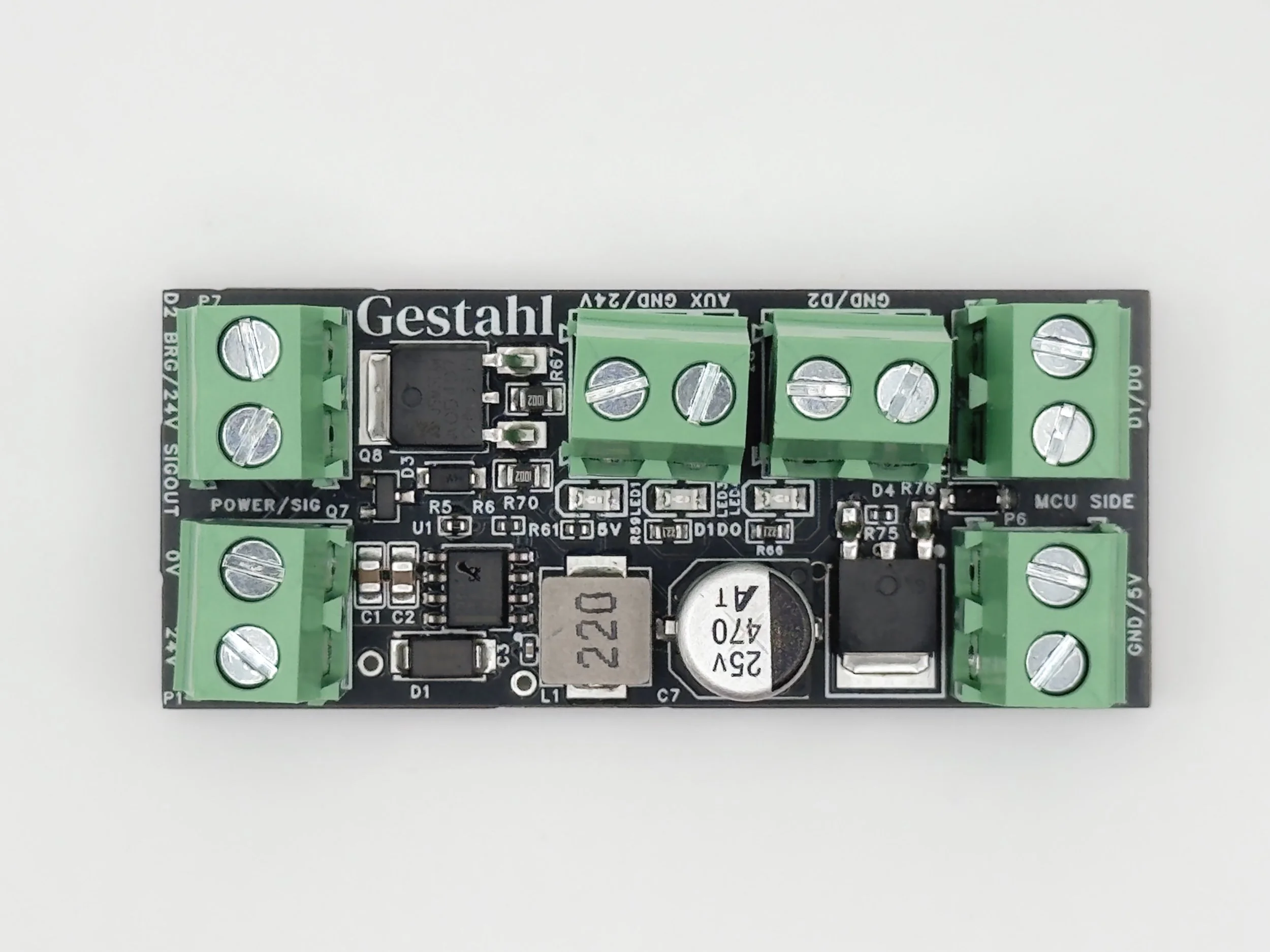
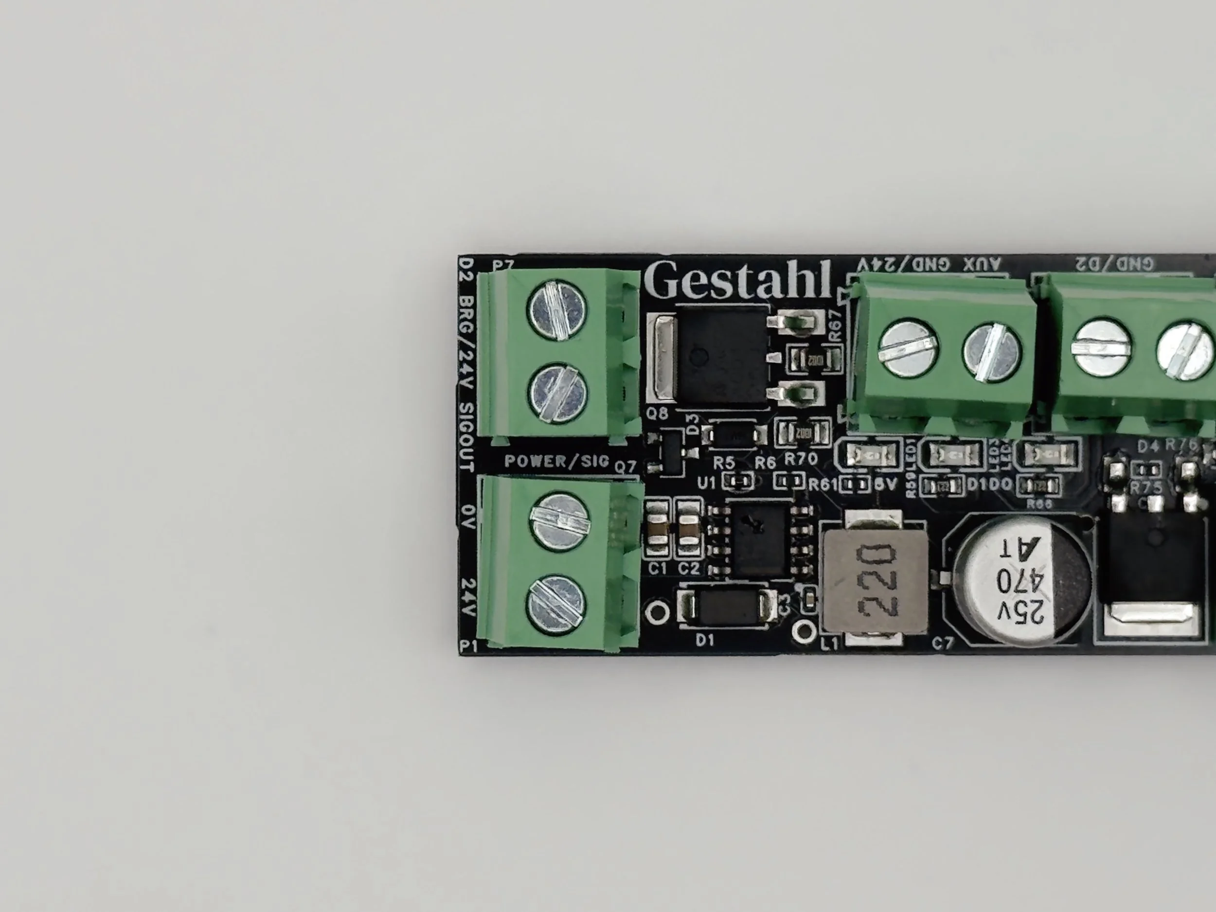
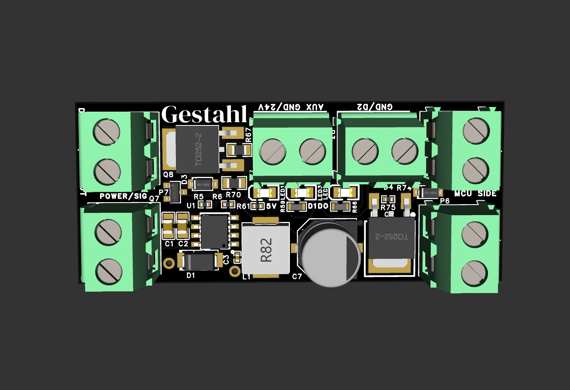
The GS-400 provides a high-side P-channel switch for generating PLC-compatible 24V signals and a low-side N-channel switch for driving solenoids, relays, lights, and other 24V loads — all from a single compact PCB.
Requires external 3.3V MCU (not included). Primary target: Seeed XIAO ESP32-C6.
Key Specifications
| Parameter | Value |
|---|---|
| Input Voltage Range | 5.5–36VDC (nominal 24VDC) |
| Regulated Output | 5.0V ±2%, 500mA recommended for MCU |
| High-Side Switch | 24V switched, 12A max (5A recommended) |
| Low-Side Switch | 17A max (5A recommended continuous) |
| Control Logic | 3.3V (5V tolerant inputs) |
| Default Power-On State | Both switches OFF (failsafe) |
MCU Requirements
| Parameter | Requirement |
|---|---|
| Operating Voltage | 5V input, 3.3V GPIO |
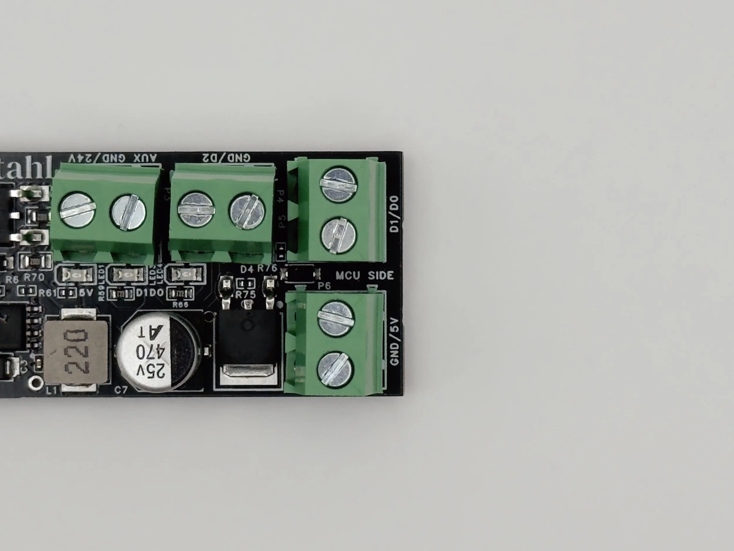
| GPIO Pins | 2 outputs (D0, D1) + 1 input (D2) |
| Primary Target | Seeed XIAO ESP32-C6 |
| Also Compatible | Arduino Nano, ESP32 DevKit, Raspberry Pi Pico, any 3.3V-logic MCU |
Environmental
| Parameter | Value |
|---|---|
| Operating Temperature | −20°C to +70°C |
| Storage Temperature | −40°C to +125°C |
| Humidity | 5–95% RH (non-condensing) |
Mechanical
| Parameter | Value |
|---|---|
| Dimensions | 68 × 37 mm (2.68 × 1.46 in) |
| Connectors | 6× 2-position 5.08mm screw terminals |
| PCB | 2-layer FR-4, 1.6mm thick, lead-free HASL |
| Mounting | No mounting holes — secure via enclosure or DIN-rail carrier |
Features
- Integrated 5V Power Supply — On-board buck converter powers your MCU directly
- High-Side P-Channel Switch — Generate 24V PLC input signals
- Low-Side N-Channel Switch — Sink current for solenoid valves, contactors, indicator lights
- Built-in Protection — Zener diode gate clamping, pull-down/pull-up failsafe resistors
- Status LEDs — Power indicator + high-side + low-side switch status
- D2 Feedback Line — Signal verification or external sensor input
Typical Applications
- PLC digital input signal generation
- Solenoid valve and contactor control
- Indicator light switching
- Small DC motor control
- MCU-based IoT industrial I/O
Compatible PLCs
Tested with AutomationDirect Click CO-00DD2-D. Compatible with Click PLUS, BRX series, Siemens S7-1200 DC/DC/DC, Allen-Bradley Micro850/870, Schneider M221/M241, Mitsubishi FX5U, Omron CP1L/CJ, and IDEC MicroSmart FC6A. Use PLCs with 24VDC sink/source digital inputs.
Regulatory & Compliance
| Requirement | Status |
|---|---|
| RoHS 3 | Compliant — Directive 2011/65/EU + Delegated Directive (EU) 2015/863 |
| Component Selection | All components specified as RoHS-compliant |
| PCB Finish | Lead-free HASL |
| Solder Paste | SAC305 (Sn96.5%, Ag3.0%, Cu0.5%) |
| Third-Party Testing | Not performed — compliance based on component specifications and manufacturing process |
Package Contents
- 1× GS-400 5V PSU + MOSFET Switch Board (V1.2)
- Product documentation (HTML download)
Note: MCU not included. Board requires external 3.3V microcontroller for operation.
Installation & Safety
Intended Use: The GS-400 is a subassembly intended for integration into larger systems by qualified electrical and automation professionals. This product is not a consumer device and requires an external MCU for operation.
Installation Environment: Must be installed in a properly rated enclosure (NEMA/IP) with appropriate strain relief and cable management. Enclosure not included.
Thermal Derating: Both switches rated for 5A continuous at ≤40°C. Derate to 4A at 50°C, 3A at 60°C, 2A at 70°C. Do not operate both channels at maximum current simultaneously without thermal analysis.
Failsafe Design: Both switches power up in the OFF state. Pull-down and pull-up resistors ensure safe default state during MCU boot or GPIO float conditions. Verify failsafe behavior is appropriate for your application.
Inductive Loads: When switching inductive loads (solenoids, relays, contactors), install appropriate flyback protection at the load. The board does not include load-side flyback diodes.
Exclusions: The GS-400 is not designed, tested, or certified for safety-critical applications, life-support systems, applications requiring SIL-rated components, explosive or hazardous atmospheres, or direct outdoor installation without appropriate enclosure.
Warranty: Warranted against defects in materials and workmanship for thirty (30) days from date of shipment. Warranty does not cover damage from misuse, improper installation, operation outside specified limits, inductive load damage, or integration failures.
Limitation of Liability: Gestahl's liability is limited to repair or replacement of defective products. In no event shall Gestahl be liable for incidental, consequential, or special damages arising from product use.
Specifications Subject to Change: Specifications and features are subject to change without notice. Consult current documentation at gestahl.com for latest information.
Part Number: GS-400
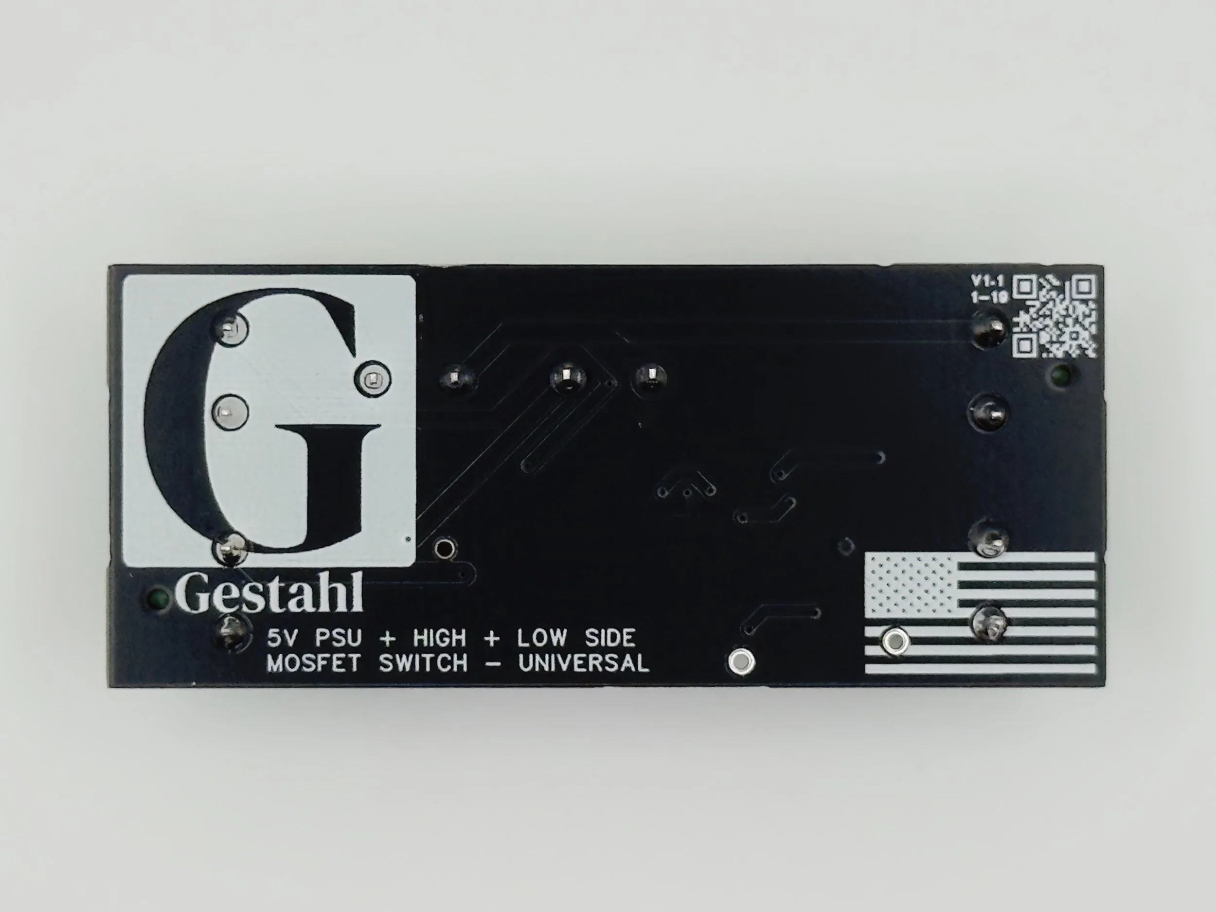
Current Version: V1.2
Revision History
| Version | Changes |
|---|---|
| V1.0 | Initial Release |
| V1.1 | Increased MOSFET VDS Limit |
| V1.2 | Improved Header Silkscreens For Clarity |